The importance of proper start-up procedures in any boiler application are often overlooked. Some tasks during the process of initiating a boiler’s first fire are critically important to safe, efficient operation and component lifecycle. Missing a step could cause damage to the boiler system and impact the unit’s efficiency for the life of the appliance.
The first thing to check before start-up is the boiler’s “AO” – or area of operation. Make sure there is no trash, debris, or anything flammable nearby. Check for any potential sources of trouble: for instance water leaks, or the smell of gas. Ensure that all physical characteristics of the environment such as support for the boiler, insulation, piping and brackets are secured. Make sure everything looks right; that there are no sources of concern.
Since a boiler’s main purpose is to heat water efficiently and reliably, it’s important to conduct a water quality test, ensuring that the water entering the boiler through the feed valve is of acceptable quality. Water quality is one of the most important facets of a boiler’s operation. Boiler loop water must be properly conditioned and free of sediment or impurities. Make sure you valve off the boiler before cleaning the system piping. Hardness, which can cause scale buildup within the heat exchanger, and pH must also be adjusted by a water quality contractor to meet the pH and hardness requirements in the O&M Manual.
Since air is required for proper combustion, make sure the air intake is free of any obstructions and sized properly to support the required CFM.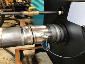
Check system exhaust piping as well to assure there are no obstructions and the flue has been sized properly to meet the required pressures listed in the O&M.
If you are using an engineered vent system with a draft assist, be sure to check the operation of draft fan as well as the proving switches.
Here’s an at-a-glance checklist for safe start-up:
- Check for fuel leaks with the a gas sniffer or bubble test.
- Connect the flue gas venting to the boiler to ensure that all gases are distributed outside the building.
- Connect gas and inlet/outlet water
- Identify boiler water, gas, and electrical connections, and other safety
- Make sure the dipswitches on PCB06 are in the down
- Locate manometer pressure taps for pressure measurements in the following areas:
- Supply gas pressure (supplied ball valve tapping should be piped to the inlet side of the supply gas.
- Other areas?
- Install the gas analyzer probe within 6” above the flue gas
- Check high and low gas pressure switch settings:
- High gas pressure switch at 0” w.c. (outlet side of gas valve)
- Low gas pressure switch at 0” w.c. (inlet side of gas valve)
- Program the Concert display and SOLA control if necessary for boiler pump, remote sensor, outdoor sensor, and outdoor reset if using outdoor sensor.
- Open the supplied manual ball valve added to the supply gas piping. Bleed-out any air trapped in the gas train from the ball valve tapping.
- Reset the low gas pressure
- Open the manual gas valve between the automatic gas valve and the blower inlet.
- Cycle the The boiler should establish main flame. If flame is not established, adjust shutter valve ¼ turn to the + side. (Do not adjust beyond 3 full turns. Apply troubleshooting techniques to find cause.)
- The boiler must be running to use manual mode.
- To Lock the boiler in manual mode, tap the nine dots on the display. tap Operation, Tap the lock at the top and type 86 enter. The lock should turn green. Tap high/low, tap manual mode, tap The Boiler will ramp up to high fire. Once boiler has reached high fire rate, adjust combustion to O2 levels of:
- Nat Gas 4 to 6 % O2
- LP 4 to 6 % O2
- with all jacket doors installed and front cabinet door closed
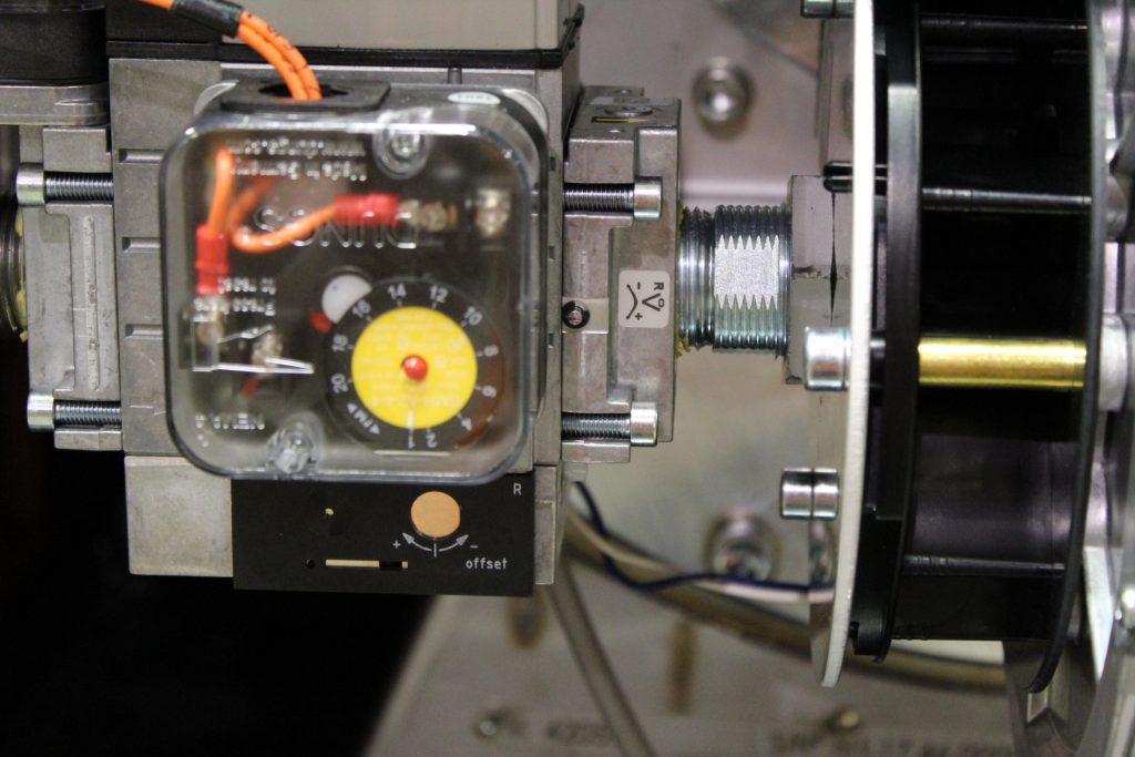 Note: High Fire O2 levels are adjusted with the gas shutter valve located on the outlet of the gas valve. (small slotted screwdriver)
- Turn adjustment screw toward the ‘Plus (+)’ side to increase gas flow (and decrease O2 level).
- Turn adjustment screw toward the ‘Minus (-)’ side to decease gas flow )and increase O2 level).
- Go to back manual mode: hit low. Boiler will drop to low If required adjust the O2 with the Offset.
Note: ONLY ADJUST LOW FIRE OFFSET IF YOU ARE OUT OF RANGE. Low Fire O2 levels are adjusted with the offset adjustment located on the bottom of the gas valve (shutter may be closed from the factory, hiding the adjustments).
High and Low Fire Adjustments on the Main Gas Valve Regulator
Once the boiler is operating within the specified high and low fire ranges, record emissions (print out high and low fire O2 readings).
Record flue gas and ambient temperature, and verify flue gas temperature does not exceed 200 F.
In an event the flue gas temperature is above 200 F, apply troubleshooting techniques to find the cause.
These tests, observations and precautions will result in the safe, reliable and efficient operation of the boiler. The old adage applies: An ounce of prevention is worth a pound of cure.